Flashlight - 2021
Getting a decent quality high-power flashlight is not easy when sellers are exaggerating or straight-up lying about their product's performance. The "rated" lumen output has (almost) nothing to do with the real brightness. At worst, the seller is lying completely; at best, the lumen output ignores the power loss over the lens and reflects just the absolute maximum ratings according to a datasheet of the LED inside, regardless if the flashlight is actually capable to provide the necessary current and sufficient cooling. And the only truly serious products are either too big or too weak...
I wanted something small and powerful, so I started to build my own flashlight (that you can see in the video) with the following design requirements/objectives:
tiny pocket size body with a small 14500 Li-ion inside,
as much lumen output as possible,
linear drive with Attiny10 as a controller,
constant current drive,
low battery voltage cutoff,
reverse polarity protection,
LED overheat protection.
I wanted something really small and lightweight, so it would not bother me while carrying around. That's why the 14500 battery was chosen as opposed to a more common 18650. The linear drive was chosen because of its simplicity and effectiveness. In single-cell flashlights such as this, linear drive is about 80% efficient, getting closer to 90% as the cell discharges. Step-down drivers, although more efficient, have a problem that there is a silicon diode in series with the load (LED). If a step-down driver is used, the voltage drop on the diode limits the maximum power output of the flashlight when the battery is at lower charge levels. It can be mitigated by using a bootstrap step-down driver, but that increases the complexity a bit too much for what I've pictured.
The schematic I designed to comply with everything above looks like this:
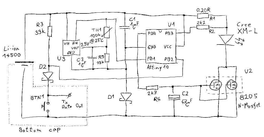
The circuit is powered by a 14500 Li-ion battery with 800mAh, and the light is produced by a Cree XM-L LED. The LED is driven using 8205 N-MOSFETs connected in parallel and operated in their linear region by an Attiny10 microcontroller. 8205 is commonly used in BMS circuits; it has low on-resistance and low Vgs voltage, which is required to reduce the drain-source voltage drop in this circuit to the minimum. The 8205 is controlled by a PWM signal smoothed out using a low pass filter (R4, C2). With a PWM frequency of 8 kHz, the attenuation is about -76 dB which I pretty much consider as DC. The filtering of the PWM introduces a slight lag in the system, but nothing serious... it actually helps with smoothing the transitions in brightness levels.
The current is measured on the RESET pin of the Attiny10 microcontroller as a voltage drop over the R1 shunt resistor. Since the RESET pin is still used for resetting the controller, the voltage should not drop below 90% of VCC (according to Attiny10's datasheet). In this application, however, it is not an issue because even at high currents the voltage drop over the resistor is small enough that it does not exceed 10% of the supply voltage.
Attiny10 does not have an internal voltage reference, so to measure the supply voltage (and therefore the battery voltage), an external voltage reference was added in the form of a 2.5V linear regulator U3. When enabled, it has about 100uA quiescent current consumption, which would drain the battery too quickly. So pin PB1 grounds the enable pin when the flashlight is turned off. Measuring the voltage reference is done by pulling PB1 high, waking up the regulator then setting PB1 as input and measuring the voltage through thermistor TH1.
The temperature of the LED's die is measured using a 100k thermistor TH1 placed next to the LED with some thermal paste to lower the thermal resistance. The temperature is calculated from the resistance of TH1, which is measured as a voltage divider between TH1 and an internal pull-up resistor on pin PB1. Resistor R5 ensures the lower end of the voltage divider stays at 2.5V. By measuring the voltage on PB1 and knowing the supply voltage and internal pull-up resistor value (37kOhm), one can calculate the resistance of TH1 and, therefore, the temperature.
PB1 wins the contest of utility... it is used as an output to enable U3, measures the voltage of U3, and measures the temperature of the LED using thermistor TH1!
The reverse polarity protection is ensured by diodes D1 and D2, together with the power LED. The only path for a reverse current is through resistor R4, which is sufficiently high to limit the current and prevent any damage if the battery is accidentally reversed. D1 increases the minimum gate voltage on the 8205 to about 0.2V above GND. Fortunately, it is not enough to introduce any measurable current through the power LED, so the quiescent current of the whole circuit stays negligible.
The flashlight is controlled by a button connected to PB2. The same pin also transmits some internal variables for debugging and monitoring purposes using UART format with a baud rate of 38400.
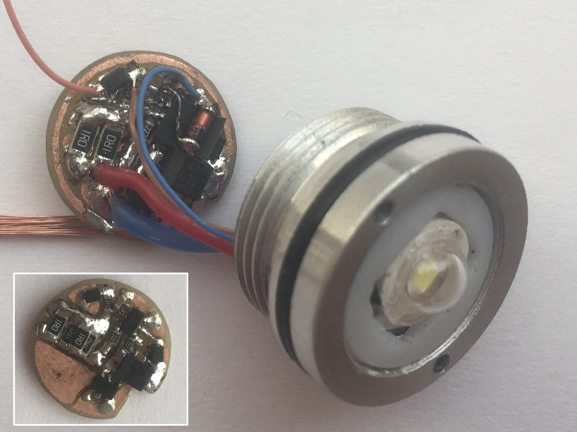
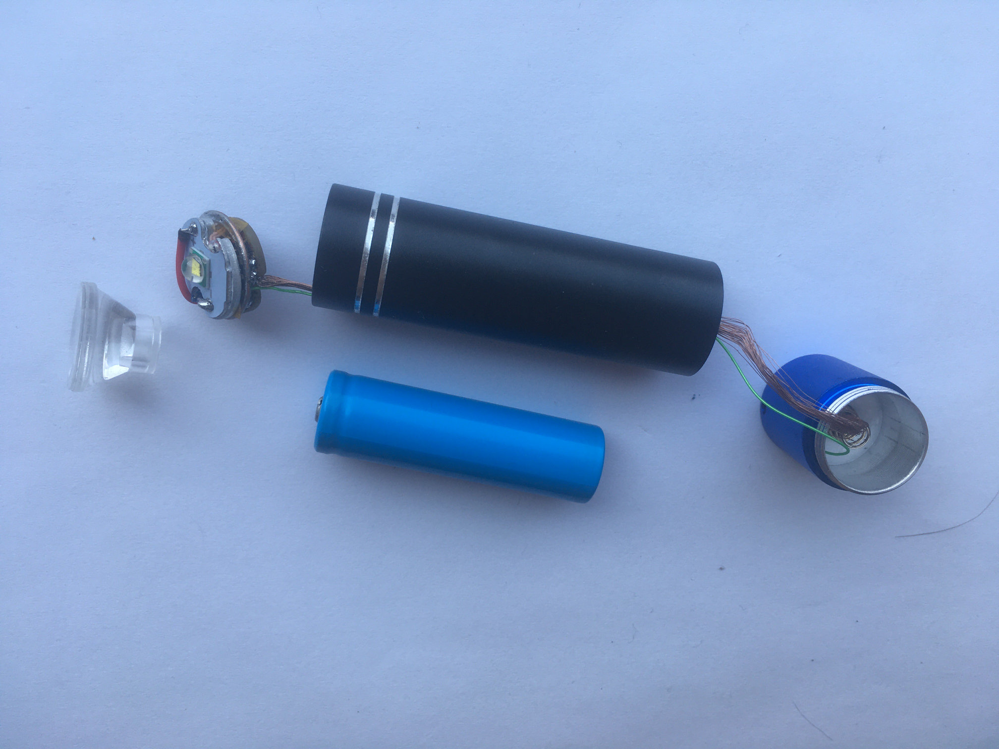
The completed double-sided PCB has about 14mm in diameter. One side serves as a contact point for the positive terminal of the 14500 Li-ion, and the other side holds electrical components. Missing on the PCB is the power LED, thermistor, and push button. I used a cheap flashlight to mount the circuit in, attached the thermistor to the power LED with some thermal paste, and placed the push button in the removable bottom cap of the flashlight. Most flashlights use the entire body as a negative terminal that connects the circuit to a battery via a switch (turning on the flashlight). I consider that to be a superior design to mine, but because my design needs to be constantly powered and also requires the button as an additional signal, I had to connect the bottom cap (the button) with the circuit using two wires, one for the battery's negative terminal and one for the button.
The firmware is written almost entirely in assembler, considering the tiny 1kB FLASH memory inside the Attiny10. When turned off, the microcontroller is in power-down mode consuming less than 0.2uA. When turned on, a closed-loop PID regulator controls the duty cycle of the PWM, driving the gate voltage on 8205 MOSFETs. The drive current for the XM-L LED is set to 1.6A. Even though the XM-L can withstand higher currents, the SOT23-6 package of 8205 and 14500 Li-ion battery discharge rate (2C for an 800mAh battery) are limiting factors here. When the low battery voltage threshold or the maximum LED's die temperature threshold is reached, the brightness decreases such that these limits are not exceeded.
The user interface is kept simple. Clicking the button turns the flashlight on/off, and holding it lowers the regulated current from the initial 1.6A or shows the battery charge level.
Now, let's look at the performance. The following plots are made from recordings of the internal variables transmitted on PB2.
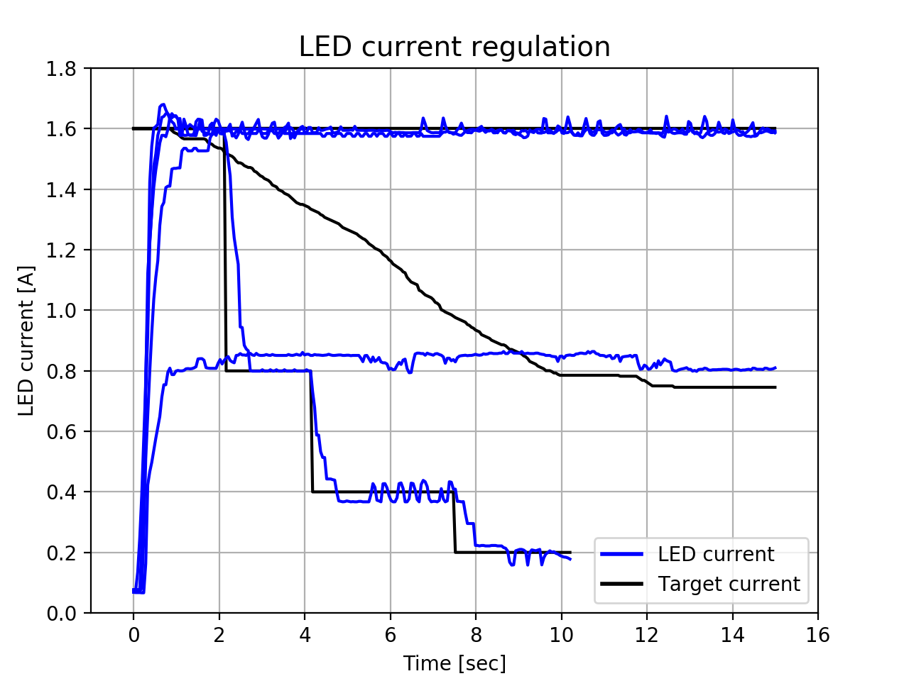
The first plot shows the start-up of the flashlight and regulation of the current through XM-L LED. It takes somewhere between 0.5 and 1 second to reach the target current. This "slow" time response is deliberate to keep the transition smooth. If the battery is so low that it can not reach the target current, the firmware slowly decreases the target to prevent over-discharge. By holding the button, the brightness is decreased by halving the target current to 0.8, 0.4, 0.2, and finally 0.1A.
You can see significant noise and oscillations in the data. The cause is primarily the low resolution of the Attiny10 ADC of only 8 bits, which significantly limits the precision of the current measurement on resistor R1 and sometimes causes oscillations between two adjacent 8-bit values. Although a moving average of the ADC samples or other techniques might improve the precision, the regulated output is already sufficiently attenuated and small enough that these imperfections can not be noticed by the naked eye, and the output brightness seems perfectly stable.
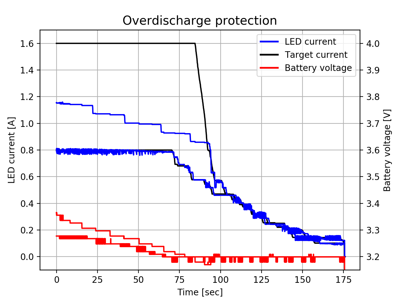
When the battery gets discharged, it can no longer deliver a full 1.6A of power. The two runs in the Figure above show over-discharge protection from different target currents. In both cases, the firmware limits the target current to prevent the battery from getting below 3.2V. The target current slowly drops to 0.1A, at which point the flashlight turns off. This happens in minutes from the point where the battery can't produce full power, meaning that for the majority of the runtime, the circuit is able to produce the full 1.6A of power and struggles only in the last couple minutes, right before the battery is almost discharged. Again, you can notice the low resolution in the battery voltage measurements caused by the low-resolution 8-bit ADC.
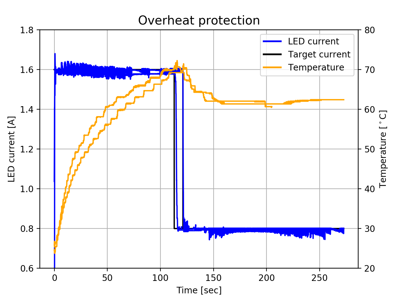
The final plot shows the overheat protection. The threshold is set at 70 degrees celsius on thermistor TH1, but considering the thermal resistance between the thermistor and the LED's junction, the junction is probably somewhere between 80-90 degrees celsius. When the flashlight is in still air (visualized in the plot above), it takes about 2 minutes to trip the overheat protection. It is actually possible to keep the temperature below the threshold even at full power (1.6A*3.6V>=5W) just by holding the flashlight in hand, although it gets quite uncomfortable pretty quickly.
I've also assembled a second flashlight from leftover spare parts. The second one is slightly bigger and has only a 1W LED, but with less power comes also a longer battery life and no overheating.
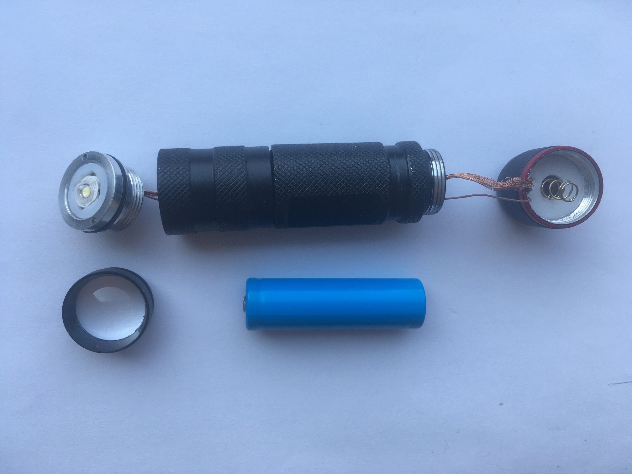
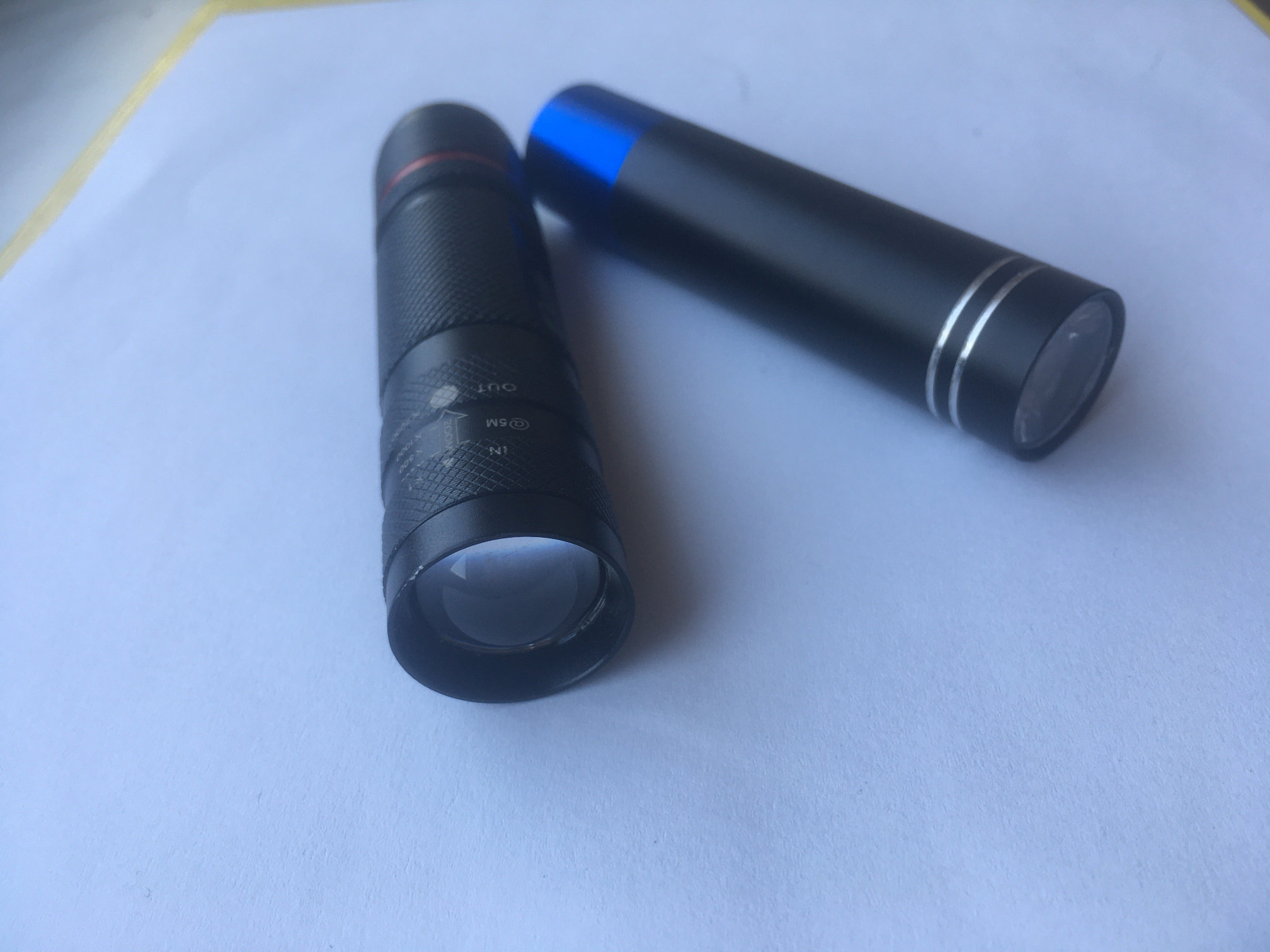
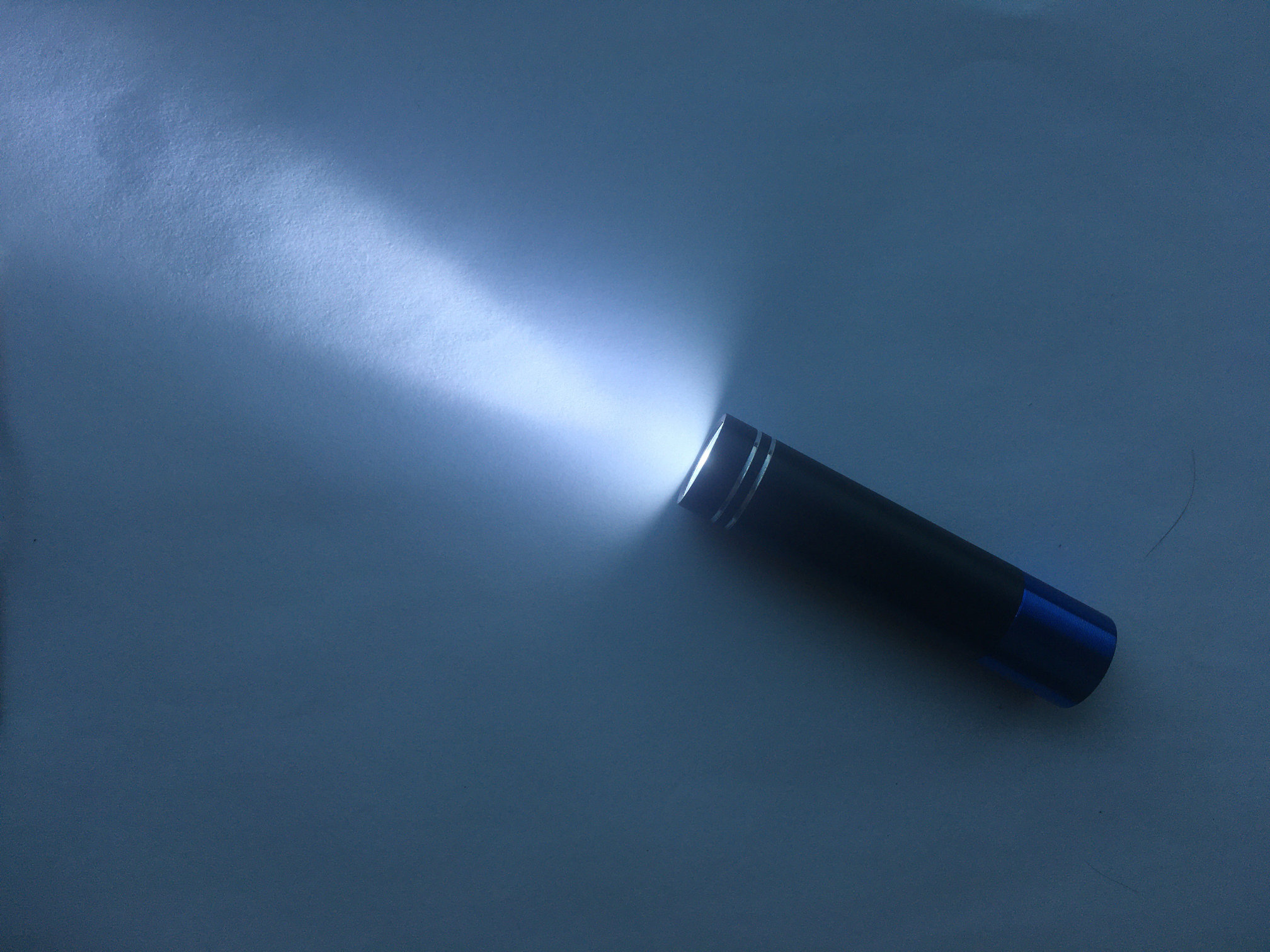
The smaller flashlight with XM-L LED, the one I carry daily, completely discharges in under 30 minutes (2C), consumes more than 5W (3.6V*1.6A), and produces around 400 real lumens (500 lumens according to datasheet minus 20% loss across the TIR lens). It draws less than 1uA when off, has active over-discharge and overheat protection, and with dimensions of only 19mm in diameter and 84mm in length, it is way smaller (although slightly less powerful) than any 18650 flashlights.
The objective of creating an overpowered small flashlight was pretty much met; one could replace the linear drive with a bootstrap converter for slightly better efficiency and longer battery life, use an IMR lithium cell for discharge rates higher than 2C, use a microcontroller with more precise ADC for smoother current regulation, or use a premium power LED for maximum power output at the same current. However, I am satisfied with the final flashlight and will leave these improvements for another time.
Firmware and schematic can be downloaded here.
Copyright © 2023 Jiri Stepanovsky. All Rights Reserved.